TEAM Workshop Problem No. 19
Microwave Fields in a Loaded Cavity Resonator
A. Bossavit, J. F. Lamaudiere, B. Maestrali
Electricite de France, 1 Av. du Gal de Gaulle, 92141 Clamart
Fax 33-1-47654118, E-mail: A.Bossavit@cli70or.edf.fr
Abstract. Proposed problem for the TEAM workshop: microwave
field in a loaded cavity.
The benchmark
As anounced in previous workshops, a test cavity has been built and tested
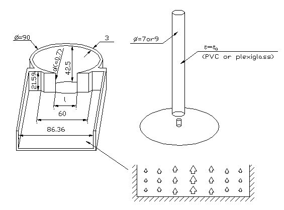
at EdF. A standard 86, 36 x 43.18 mm waveguide abuts on a cylindrical
cavity, closed except for rectangular iris. (Cf. Figs. 1 and 2. All
dimensions are measured inside the cavity. The metal sheets are 3 mm
thick, and made of electrolytic copper, sigma=4.7E7 S/m.) There are two
symmetry planes, one horizontal and one vertical. The iris height is 43.18
mm, an d its width is variable. The electric field at the entrance of the
waveguide is shown in Fig. 1 (TE 10 mode). Measurements give the
standing-wave ratio (actually, the entry S11 of the S-matrix), as a
function of the frequency. Fig. 3 is typical in this respect. The resonant
frequency is immediately read off these figures.
The cavity may be empty, or loaded as shown on Fig. 1, by inserting a
vertical rod of either plexiglass or PVC, whose diameter is either 7 or 9
mm. Best estimates for the eps_rel=eps/eps0 of these materials are:
eps_rel=2.7-0.01 i
(plexiglass) and eps_rel=4-0.1 i (PVC). There is some uncertainty about these
values, and this is the weak point of the benchmark. On the other hand,
the monitoring of the frequency and of the SWR is quite accurate.
The resonant frequency has been detemined for a series of increasing
values of the iris width, and for five different loading conditions: empty
cavity, PVC and plexiglass rods of diameters 7 and 9 mm. Results are
displayed on Fig. 4. The parameter in abscissa is the width l of the
iris. This width was steadily increased, day by day, over a period of few
weeks in June and July 1992, by careful, hand-made and eye-controlled,
machining. Each time, measurements were taken for all loading conditions.
The cavity must be dissambled between two experiments, and because of the
unavoidable play, its dimensions are never quite exactly the same. Fig. 5
shows the irregularity in the frequency response due to this factor. There
is an erratic error on the resonant frequency. We believe the absolute error
to be less than 1 MHz. ¹
Some impedance values are also available (Cf. Fig. ^, and the zoom in Fig.
7). Upon comparison between Figs. 6 and 5, we believe the measurement-points
marked '?' to be spurious.
Suggested computations
- Assume the iris-width l=15 mm and the 9 mm plexi rod. For a
series of values of the frequency in the range 2400-2600 MHz, compute the
electric field in the cavity, as excited with the TE10 modeof Fig. 1, and
determine the highest magnitude. Plot this against the frequency. Locate
the resonance peak. Do the necessary complementary computations to plot
the frequency in a 10-MHz wide range around the resonance frequency thus
determined. (Increments of 1 MHz or less are recommended.)
- Give visualizations for both fields e and h at the
resonance value (e in the vertical symmetry-plane and h in
the horizontal one), at phase 0. (Optional: give plots of both
fields in the plane of the iris. We plan to make infrared thermography
measurements there in a not too distant future.)
- Still with l=15 mm, and for all five loading cases, try and
locate the resonant frequency, by the above method or any other method.
- If computing resources are sufficient, do this for other iris-widths
as well.
- Suggested themes for discussion:
What is the dependence of this results on eps' and eps''?
How sensitive are they to the shape of the aperture? How critical is the
modelling of this part of the cavity, especially as regards the width of
the iris wall (d in Fig. 1)? How important is it to refine the
mesh in the load and near it? How beneficial are mesh-refinement
procedures?
¹ In a few cases, we have two measurements on the same configuration,
before and after a full dissassembly, to confirm this estimate: at
l=15 mm, no load, 2.54538 the first time, then 2.54454, i.e.,
Df=0.84 MHz; at l=15.5 mm, with the PVC9 load, Df=
0.6 MHz.

Figure 1
Left: the lower half of the cavity.
Above right: how the dielectric rod is placed (small pegs at the
bottom and at the ceiling of the cavity help center it).
Bottom, right: shape of the dielectric field in the front
cross-section of the wave-guide.

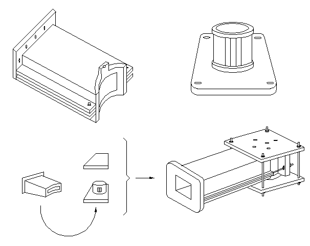
Figure 2
Assembly of the cavity from its main pieces:
the slitted cylinder, the rectangular waveguide, the upper square
flask.
Bottom, right, the whole apparatus.


